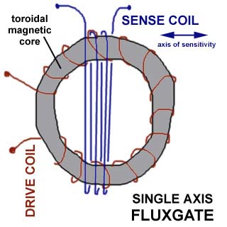
I have drawn above a quick sketch of the windings of a toroidal-core, single-axis fluxgate: that is, it responds to the magnetic field vector along the indicated axis of sensitivity. Note that the red wire (drive coil) is wound closely around the core, passing through the central hole on each turn. The blue wire (sense coil) is wound around the outside and does NOT pass through the central hole at all. I have drawn a few windings for clarity but in practice, for best sensitivity, both drive and sense windings might have 100 turns or more. With this type of core you can get two orthogonal axes of sensitivity for almost the price of one, just by winding another sense coil over the first but at right angles (the wires would run horizontal in the picture above, and the axis of sensitivity would be up-and-down.)
You can also make a single-axis with a simple rod core: in this case you wind the sense and drive coils over each other (or side by side) and you can get only one sensing axis (along the core) per fluxgate.
Almost any metal or ferrite will do for the core; when you want good sensitivity then you use special high-mu materials. I happened to use a random core from Haltek Electronics in Sunnyvale, CA (36 mm OD, 8 mm thick, partly copper-clad, marked "2299926-2C AL729").
For those interested, I provide an outline of the circuit I used to make a fluxgate. This is a simplified version of the article's [1] circuit with a non-optimal core; even so, I was able to pick up fluctuations in the earth's field of 20 gammas or so. Since the ambient field is fluctuating at least that much constantly, it's hard to determine if you have better sensitivity unless you have an active nulled Helmholtz-coil system to provide a more stable local field, or a magnetically-shielded room (which I didn't have). I was able, for instance, to see clearly someone rolling a metal cart through the hallway about three meters away.
Circuit Outline [gif] [postscript]
Circuit Notes: the 'snubber' diode to -12 V should point AWAY FROM
the -12V supply.
You can use any garden-variety transistors and flip-flops you want.
Nothing is critical, this is low-power, audio-frequency stuff. You can
make the op-amp gain stages inverting or not inverting, as you choose-
you will find it just flips the polarity of the output (positive being
north or south). In general, you get better op-amp performance (offset
and CMRR) in the inverting configuration.
You don't want the sense and drive coils to short to each other, so
I recommend some insulating tape between them. There's no need to space
them really far apart, though.
You want exactly 50% duty cycle square wave to avoid any DC. That's why
I used the first divide by two after the 555 timer, so you get a nice
clean 50% duty cycle that way. You could never get as accurate a
waveform if you ran the 555 chip directly at 800 Hz. The drive
frequency is not critical, by the way, you can experiment with what
works best with your particular coil. However you do need the sense
frequency ("2-phi" driving the 4066 analog switch) to be the same
signal (matched and phase-locked to the drive frequency).
The fluxgate can measure DC or low-frequency AC fields. However, if you just want to measure AC magnetic fields there is an easier way: a simple coil of wire.
> I want to make a sensor to measure magnetic field from line current.
> Local line current is 50 Hz. If I have a core of N turns, with a loop
> area A (in square meters), crossed by a magnetic field B (in Gauss)
> (produced by an 50Hz power line) what current I (in Amperes) will flow in
> the wire?  Is this value rms?  By other words what is the relationship
> between I, B, A, N?
Faraday's Law states that the line integral of electric field around a closed curve (= the voltage you'd measure in a loop of wire following that curve) is equal to (negative) the rate of change of flux with time. Flux = (magnetic field strength x area enclosed by curve). Negative just has to do with definition of positive voltage and magnetic North or South.
Let's say F=flux=B x A. With N turns you have F = B * A * N. If your loop is fixed and the field fluctuates, you have
V = - dF/dt = - A * N * (dB/dt)If B = B0 sin(wt) then dB/dt = w B0 cos(wt) where w=2*pi*f and f=50 Hz. The RMS value of field strength if you have a sine wave is Brms = B0 / 1.414 where B0 is the zero-peak value of magnetic field.
V: volts
A: area, square meters
N: number of turns
B: magnetic field, Tesla (10000 gauss = 1 Tesla)
Substituting in from above,
  |V| = | A N (w B0 cos(wt)) |

 or (V)rms = A * N * 2 * pi * 50 Hz * (B)rms
As you can see, you get linearly more voltage for a given field, by increasing the loop area, or the number of turns (or the AC line frequency :-). If you have a single turn, square loop of wire 10 cm on each side, and a 50 Hz AC magnetic field of 100 gauss RMS (0.001 Tesla) you have
V = 0.01 m sq. * 1 turn * 2 * 3.14 * 50 Hz * 0.001 T = 3.14 millivolts (RMS)
If you had 100 turns, it would be 0.314 volts, and so forth. By the way, the same law can be applied to the situation in which the field is fixed and you change the projected area of the loop (eg, by rotating it in the field). The projected area goes to zero as the loop turns edge-wise to the field, and a maximum with the loop plane normal (face-on) to the field lines. The voltage developed around the loop changes accordingly. This is how electricity is generated in a power plant, by rotating large coils of wire in a strong magnetic field, at a 50 Hz or 60 Hz rate depending what country you're in.
I can't say anything about Magnetic Research Inc. other than their web page looked like it might interest the magnetic-sensor hobbyist or engineer (?). I haven't purchased anything from them, though if I had the time to be playing around with this stuff, I probably would.
[2] "DIGI-COMPASS", T.E. Black, Radio-Electronics,
Nov. 1989, p. 43-51,82.
a computer interface to the (discontinued?) Radio Shack fluxgate
car-compass.
The RS device interestingly included an air-core resolver for analog
output.
[3] "A Review of Magnetic Sensors", J.E. Lenz,
Proc. IEEE 78 (6) 1990 p. 973
Brief review of 11 types of mag. sensors including fluxgate.
[4] "Recent Advances in Fluxgate Magnetometry", D.I. Gordon, R.E. Brown, IEEE Trans. Magnetics v.MAG-8,1,1972 p. 76-82 (45 references)
Nice explanation of fluxgate operation, graph showing sub-gamma level stability.
![[gif]](circ_out.gif)